Mississippi State University
2016 Formula SAE
— DRIVE TRAIN LEAD —
In 2015 I joined the Formula SAE team at Mississippi State university to learn more about how to build a high performance engine. I had already built the engine in my 67 Cougar, but I wanted to build an engine that wasn't limited by street driving conditions. In 2015 as a freshman in college, the team soon discovered I could tune engines so I became the tuner for the 2015 racecar. After doing well in 2015, the team promoted me to powertrain leader to begin the development of a race motor to run in the 2016 competition. I spent 1500 hours over the course of 9 months developing and building the 2016 race motor and the end result was exactly what I had hoped to get out of the engine.
Inertia Tuning
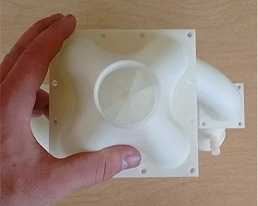
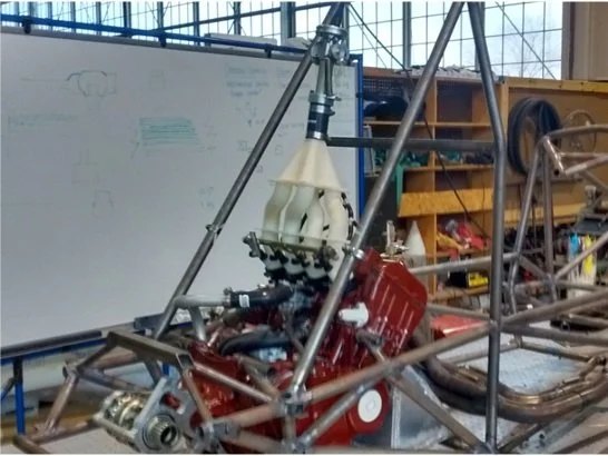
Inertia tuning is the use of specifically sized tubes for the intake and exhaust to take advantage of the inertia stored in the moving air charge. Air is a compressible fluid, and when it has velocity in a tube and that tube is suddenly shut off the air compresses then releases and flows the other way. The intake design I used takes advantage of the air bouncing effect and was theoretically sized to make peak torque at 12,000 RPM which was verified on the dynamometer once the engine was built. Notice the third picture has an intake with a black lower half and a white upper half. The intake was designed to be modular so intake runner length could be tuned on the dynamometer for maximum performance. The exhaust got the same inertia tuning design as well with a 4-2-1 header design and equal length runners. Myself and the grad student that was over the team developed a MathCAD sheet to calculate runner length and verified it from calculators online.
Engine Modifications
The main focus of the engine was to produce maximum power possible through a restrictor naturally aspirated. To do that, the biggest modification was to get custom ground cams to move the peak torque to 12,000 RPM or higher. After getting custom cams with over 320 degrees of duration on intake and exhaust, I ordered CNC machined pistons to bring the compression ratio up to 13.2/1. I decided 13.2/1 was not enough compression so I machined the cylinder head down .020" to bring the compression to 15/1. To increase the flow of the cylinder head, I "back cut" the intake valves and polished the exhaust ports cutting any flow intrusions out of the ports. To handle all the extra power, the block was bored and recoated with a thicker layer of Nik-A-Sil in the cylinder walls. For the piston rings, Total Seal piston rings were used to decrease blowby and increase efficiency.

